When looking for guidance on how to work with electrical connectors, the general advice online is “Stop what you’re doing and contact a professional!”. While I agree in theory - and highlight where it really matters below - I’ve found it much more nuanced in practice.
I want to show you how to make a good connector for two reasons. First, I want to you be armed with the knowledge needed to cross-check qualified electricians.💬Electricians are human and as error prone as any of us. When communicated well, they appreciate a second set of eyes catching mistakes. Second, I want to make sure you can wire low-voltage cable safely and the skills between the two are largely transferrable.
Regardless of your reasoning, it’s at least worth knowing what to look for in good electrical connectors.
Whether you’re wiring a massive 480VAC cable or a tiny thermocouple, the principles of wiring connectors remain the same.
The one skill that separates bad programmers from good programmers is attention to detail. In fact, it’s what separates the good from the bad in any profession. You must pay attention to the tiniest details of your work or you will miss important elements of what you create. In programming, this is how you end up with bugs and difficult-to-use systems.
Electrical wiring isn’t difficult, but there is still good reason why electricians get paid much more than other contractors. A good electrician has an obsessive attention to detail and will go out of their way to ensure all work is safe, clean, and consistent. Good electricians do not cut corners.
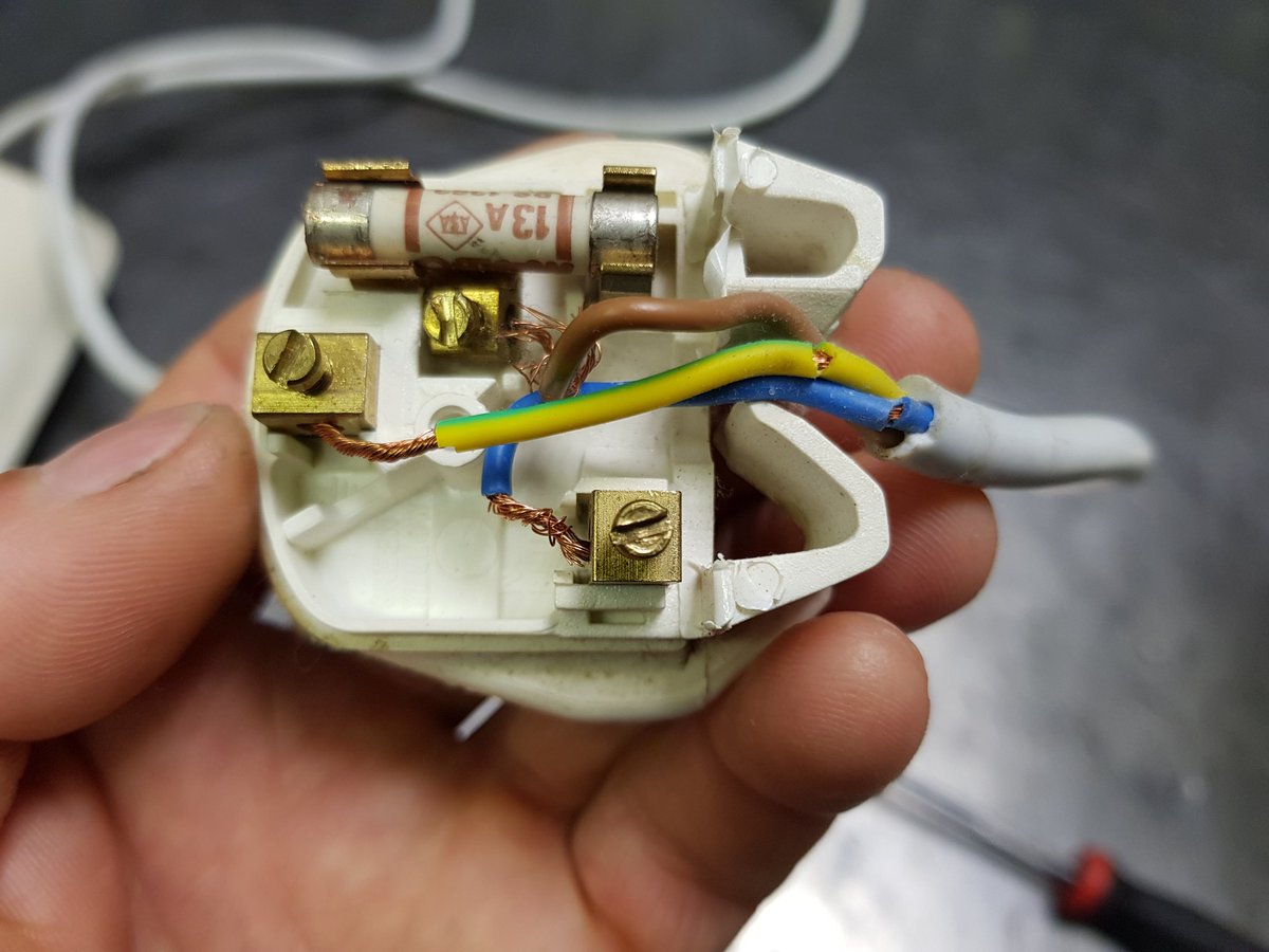
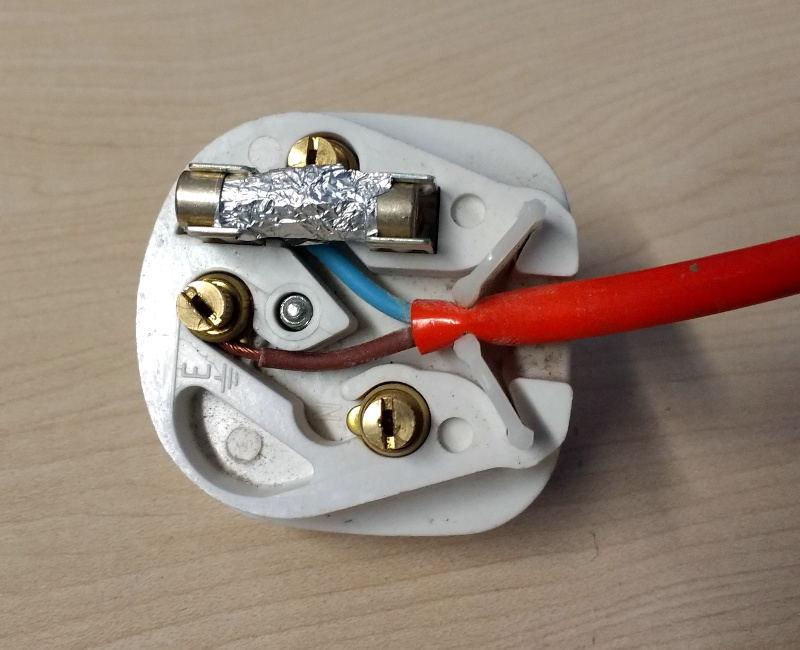
I googled “poorly wired electrical plug” and got a bunch of examples. They’re UK but the concept still applies.
| Exposed metal | No ground | Overloaded terminals | Good |
|---|---|---|---|
 |
 |
 |
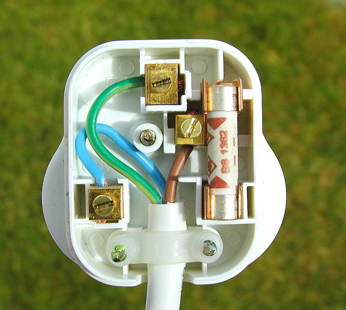 |
Side note: UK plugs are the best in the world. Read up on how to wire them here.
Cord grips protect the wire terminal connections within the connector, ensuring that they are not strained if the wire is pulled. All plugs must have a cord grip.
Let’s look back at the “exposed metal” example above:
| Exposed metal | Good |
|---|---|
|
|
This has every possible fail point.
Problem: The outer insulation was cut too far for the cord grip to work. This means that, when the wire is inevitably pulled, the strain is felt at the screw terminals (this may be why there is so much exposed wire).
Solution: Even with standards, removing the right amount of insulation comes with practice. You’ll be able to eyeball it eventually. Until then: if you remove too much, cut off excess wire until the length is appropriate.
Problem: The electrician cut into the inner insulation when removing the outer (we can see exposed metal near where the outer insulation ends). This is electrically dangerous, as electricity could arc between nearby metal. This is also physically dangerous, as the wire will fray and eventually snap over time.
Solution: When removing outer insulation, you should score, bend, and pull. Instead of cutting through the outer insulation, lightly score where you want to remove. Bend the cable around the score to start splitting the wire, and then finally pull the outer insulation off. This sounds easy but will take practice!
The above concepts apply to all types of connectors. Below are a few practical examples any specific tools and quirks worth noting.
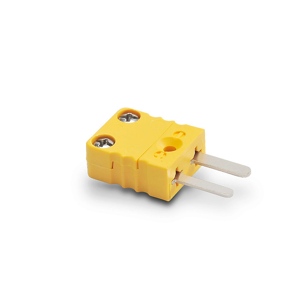
You’ll come across thermocouples as flat-pin (aka mini) and round-pin connectors.
| Flat Pin | Round Pin |
|---|---|
 |
 |
These connectors use a gasket as a cable grip. However, to engage it, you need to cut these wires very short.
Mini connectors take practice, and you’ll struggle many times before getting a feel for it. For the mini connectors, you’ll need ~1/4” stripped wire and another ~1/4” sheath. Make sure you have the gasket around the thermocouple wire, strip the leads, and then pitchfork the wires. Push both in, make sure there is no exposed metal, make sure the cable gland can engage, and that the wires are not blocking any screw holes.
The round-pin connectors are easier to use but larger. They use regular screwdrivers and have enough space to provide tolerance on your strips. They’re great in industrial environments or anywhere else the bulkiness doesn’t feel weird. The same concept applies but your cuts can be ~1/2”. Also, make sure you use a gasket that actually squishes enough to grab the cord grip.
M12 connectors, also known as “micro” connectors, are large enough to not be annoying and have enough pins to support both current (3-pin) and voltage (4-pin) signals.
M8 (aka “nano”, “pico”) connectors, are M12’s younger sibling. The M12 was released in 1985, and the M8 was released a few years after.
| M8 “nano/pico” | M12 “micro” |
|---|---|
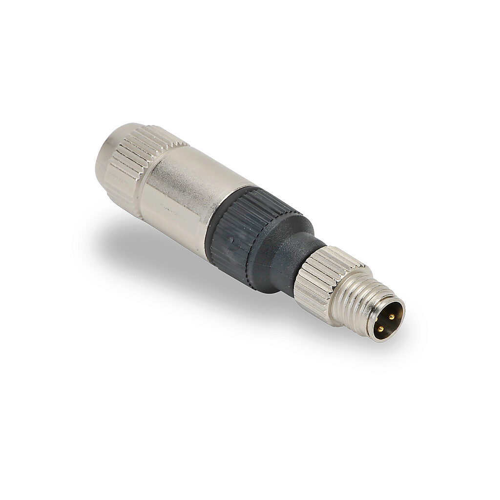 |
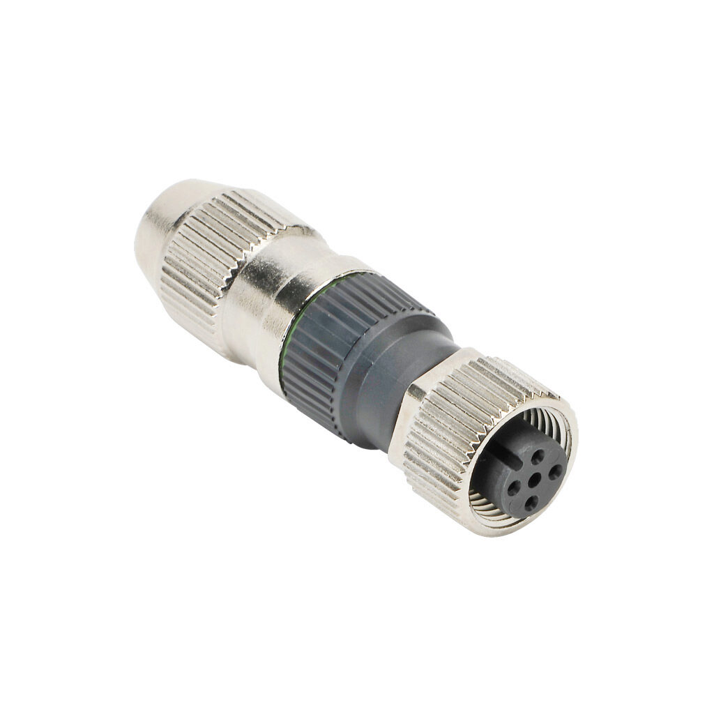 |
A thorough discussion of M8 vs M12 connectors can be found in M8 vs. M12 Connectors: How to select and implement.
Follow a wiring standard. I’d recommend AutomationDirect’s standard:
| Pin | Color | Usage | 4-20mA | 0-5V | Dual Signal | |
|---|---|---|---|---|---|---|
| 1 | Brown | +V | +V | +V | +V | |
| 2 | White | Signal | 0V | 0-5V | Input | |
| 3 | Blue | 0V | NC | 0V | 0V | |
| 4 | Black | Secondary | NC | NC | Output |
If you need to make your own connector, you can use an Insulation Displacement Connection (IDC) connection. These are much easier than fussing with miniature screw terminals. Watch this video to learn how to wire them properly.
Serial cables often come pre-fabricated from the vendor. In these cases, you should use their standard. This recommendation will solve many of your serial connector needs.
However, certain cases require making your own connector. This includes non-standard pinouts (somehow still all too common), oversized adapters, or running serial cable into control boxes. The standard custom DB9 connector uses solder cups and they’re annoying. Instead, I prefer a screw terminal version I found on Amazon:
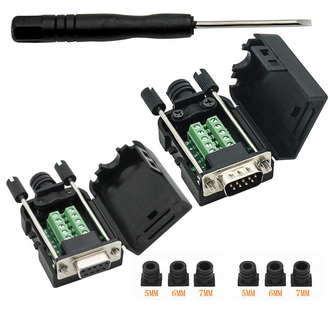
I find these much easier to use, and the integral cord grip and strain relief is a bonus. The only downside is it can get tight in there, so it will take some practice to get right.
I have found a similar screw terminal adapter on Amazon:
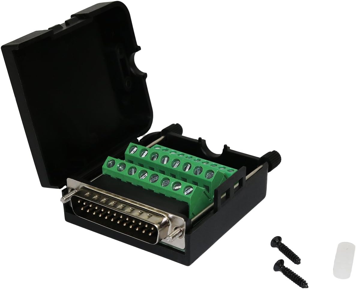
These are needed for phone lines and some PLCs. If you want to avoid using this, you can use an RJ12 ZIPLink breakout to convert RJ12 to screw terminals. However, you may sometimes find making a direct RJ12 connector to be simpler.
To make an RJ12, follow the RJ45 instructions below. Wire to T568B but without the brown wires (wo, o, wg, b, wb, g). It’ll take some practice to be able to do these quickly - don’t give up!
Not all ethernet cables are created equal! Ethernet cables come in all shapes and sizes. There are multiple standards, wire thicknesses, wire counts, shielding types, and more.
Purchasing ethernet cable off of Amazon exposes you to a world of knockoffs. Be sure to avoid. To keep ethernet cables standard and up to spec, make sure you’re buying 1000ft spools from a good vendor. This ensures that all runs use appropriate CAT6 cable.
Furthermore, there are many types of official ethernet cable. Read Know your CATS for more.
I recommend 23awg unshielded CAT6 cable, especially for PoE. Do not cut corners here; debugging a faulty ethernet cable is incredibly frustrating.
Learning how to do this right will take some practice. You will get annoyed. I promise that the pain is temporary. Just keep at it and you’ll get better.
To start, watch this video and read this guide. If you want to spend 10 minutes appreciating attention to detail, watch this video.
An important note - You do not need to strip each wire! RJ45 and similar connectors (e.g. RJ12) punch through the wire insulation when crimped. Watch the videos to see this in action.
You’ll start to appreciate that everyone has their own “tricks” for making this easier. To add to the noise, here are my tricks. These are for our specific cabling and tools so they may be more useful than others.
Check every cable with a cable tester. You may need to move the cable around in the tester jack to get all 8 leads lighting up.
Finally, remember to follow the standards. Wire to T568B (orange first), use pull-through RJ45 connectors, and point the connector away from you.
⚠️ Do not plug in until inspection!
AC power is dangerous and should be treated with respect.
For all connections, tighten the wire leads but leave the cord grip unscrewed. Find a qualified electrician to inspect and approve the connection. Keep them around for the first live use.
The US standard is NEMA 5-15, although you may encounter other connectors for high-voltage and three-phase wiring. Despite the differences between voltages and phases, the wiring concepts behind NEMA connectors are exactly the same.
Remember to use good connectors from a place like AutomationDirect, as these are tested and come with integral cord grips. Cut off as little sheath as possible (it’s tight in these connectors), flare out the wires into a pitchfork shape, push all wires in at the same time, and screw down. Gently tug each wire to make sure it’s well connected. Pause for inspection by a qualified electrician. Tighten the cord grip after approval, making sure the cord grip is actually gripping the cord.
Doing this well takes practice. You might try to screw in one wire at a time, but then find that getting the last wire in is really difficult. Don’t do this. The best way to connect multiple terminals is to splay out the wires like a pitchfork, push all the wires into the screw terminals at the same time, and then, while holding the wires in place, screw them all in together.
For more reading, check out 9 Easy Steps to Wiring a Plug Correctly and Safely. It’s a UK plug but the concepts are generalizable to all plugs.