If you’re working with physical products, you probably have a standard that specifies a power supply type. You can use that and never have to worry about this topic. That being said, learning about power supplies will help in both your understanding of electronics and your ability to improvise in a pinch.
Power comes out of the wall in the United States at 120VAC, but most electronics require a lower DC voltage to run.💬USBs are 5VDC, industrial supplies are 24VDC, PoE is 48-54VDC, and many devices are 9-30VDC. We can get from one to another with an AC-DC regulator. There are options:
| Switching Regulator, Low End | Switching Regulator, High End | Linear Regulator |
|---|---|---|
 |
 |
 |
All of these (any many more) can be used to produce a DC source. However, the results you get will vary.
As you may already know, AC current is often represented as a waveform:
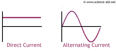
where the voltage changes with time. However, you may not have thought about what this means. In short, it’s representing oscillating flow, moving back and forth 60 times per second. If you want more clarification, watch this 5min video on AC vs DC.
In order to convert AC to DC, we need to make all the current flow in the same direction.
As chemical engineers - think of the AC vs DC current as flow in a pipe. If you had an oscillating flow in a pipe, how would you make sure flow only went one direction?
One option would be a check valve, which is a diode in the electrical world. Forward flow would be allowed and backward flow would be prevented. This would create a flow pattern like this:

In the right direction but not quite there yet (also very stressful on the check valve).
You could improve this with a series of check valves. Check out this cleverness:
This is called the diode bridge and is conceptually at the heart of most AC-DC power supplies. It produces a waveform that looks like this:
It doesn’t look pretty, but we now have all the current flowing in the same direction so we can call it DC.
If you’re curious about this, read this tutorial.
We need a specific DC voltage, and we want a more stable power supply.
Put your chemical engineer hat back on. Now that you have this pulsating flow, how would you go about reducing and smoothing it?
A capacitor is the electrical version of a surge tank, smoothing out variations in input. A 10µF capacitor is sized to roughly correspond with AC oscillation frequency, and 0.1µF capacitors (“magic pixie dust” capacitors) are roughly sized to handle high-frequency noise (e.g. radio waves, wifi). Add one and you have an Amazon-worthy power supply:
Note that this provides a smoother current but doesn’t reduce the voltage!
We could add a critical orifice to reduce the voltage, bleeding out the rest of the current and getting a smooth supply.
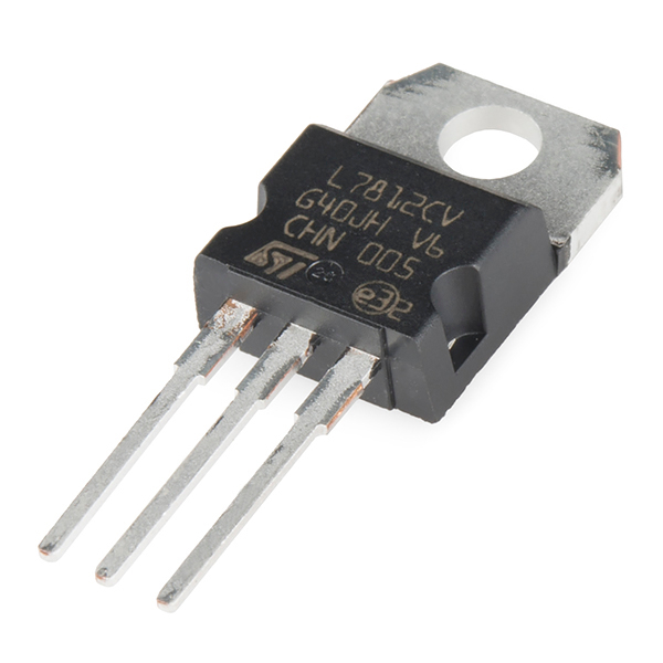
In electronics, this is a linear regulator (LR) and it does the same exact thing. It works well to provide a stable DC power supply, but it is ridiculously inefficient. LRs “bleed” out the excess current as heat, and they are prone to getting very hot.
These are useful for low current flows, like you would find on 4-20mA sensors. However, even in these situations, you probably don’t want to place an LR right after our power supply. We should have something else attempt to reduce the noise and take strain off the LR.
A little more work, but how about a shutoff valve with a pressure transducer and PID loop? The valve turns on when the pressure is low, and the valve turns off when the pressure is high. Similar effect, but far less waste.
In electronics, this is a switching regulator. Contrasting an LR, this is not a component but rather a full circuit. It works reasonably efficiently but still has some wobble.
For more, read the Bald Engineer’s Switching Voltage Regulator Tutorial.
As you can imagine, the quality of switching regulators can vary greatly. If you’re looking to build a cheap “technically 24VDC switching regulator” power supply to sell on Amazon, you could just have a transistor on a timer. If you’re looking to build a good power supply, you’ll probably have multiple high-quality MOSFETs toggling based on voltage measurement data.
For a very good power supply, you would combine this circuit with many capacitors and linear regulators (although I believe LRs are less common today). You would copy-paste this circuit a few times to further smooth the current. While you’re at it, you would thicken up the wires and add over-current protection, ensuring the regulator will not emit much waste heat and will behave safely if wired improperly.
This is the difference between the cheap and the good power supplies.
There are plenty of cases where the cheap power supply works fine. Valves, heaters, and the like certainly don’t care whether their 24VDC is slightly off. Additionally, most instruments that communicate digitally won’t notice slight disturbances (many even have onboard LRs for their sensitive components).
Analog sensors will not work well with an unstable power supply. Analog sensors send current and voltage out as their signal, and an unstable power supply will result in similarly unstable readings. If you can read your sensor fast enough, you’ll actually see the same AC oscillation in your sensory data.
If you only have cheap power supplies (or you’re making commodity equipment), then you can place a linear regulator after the power supply to create a separate low-noise circuit. Use the raw power supply for things that can take it, and reserve the regulated circuit for sensitive electronics.
If you’re going down this route, you should also place extra capacitors around your power supply. You might want to consider replacing the diode bridge with a transistor bridge, and then you can squeeze a lot of this onto a printed circuit board.
Good power supplies aren’t very expensive (maybe $80 vs Amazon’s $10). It may not perform noticeably better than the low-quality regulator with capacitors and an LR, but you don’t need to make that circuit each time you use something.
The bigger benefit is that good power supplies come with over-current protection. If you short a circuit on a cheap power supply, it will run until it explodes. If you short a circuit on a good power supply, a warning light will turn on and it will refuse to send more power. This is a great safety feature and should be included on every system you build.